 studio electronics, teardown notes, signal path analysis
Compressor
Shadow Hills Mastering Compressor: a bench-side teardown of its gain-control and transformer architecture
I've spent most of my working life around analog audio gear — repairing it, setting it up, buying the occasional piece I probably didn't need, and listening to what happens when it's pushed harder than the brochure suggests. After enough years at the bench, you get to know the usual suspects: tired power supplies, oxidized switches, drifting opto cells, noisy pots, and the small circuit decisions that make one old box worth keeping.
That's how this Shadow Hills Mastering Compressor ended up on my bench. It came in for a check-over, so I opened it up and ran it through some basic tests on an Audio Precision analyzer. The idea is simple: follow the signal, measure the circuits, and see how a well-known piece of gear looks with the lid off. Classic machines have personalities, but they also have parts, tolerances, aging patterns, and the occasional bad surprise. A bench tells you which is which.
Exterior and working surface
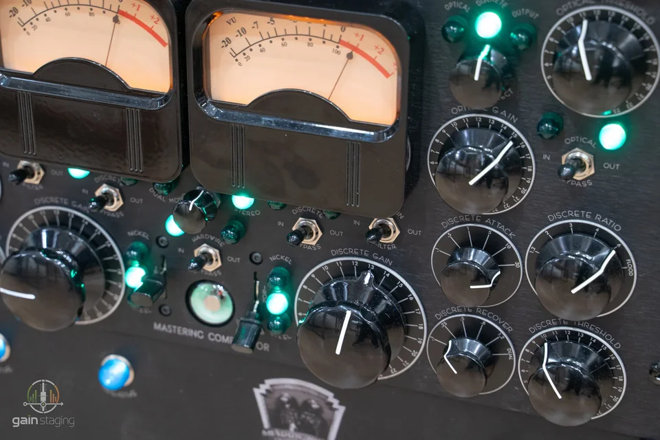
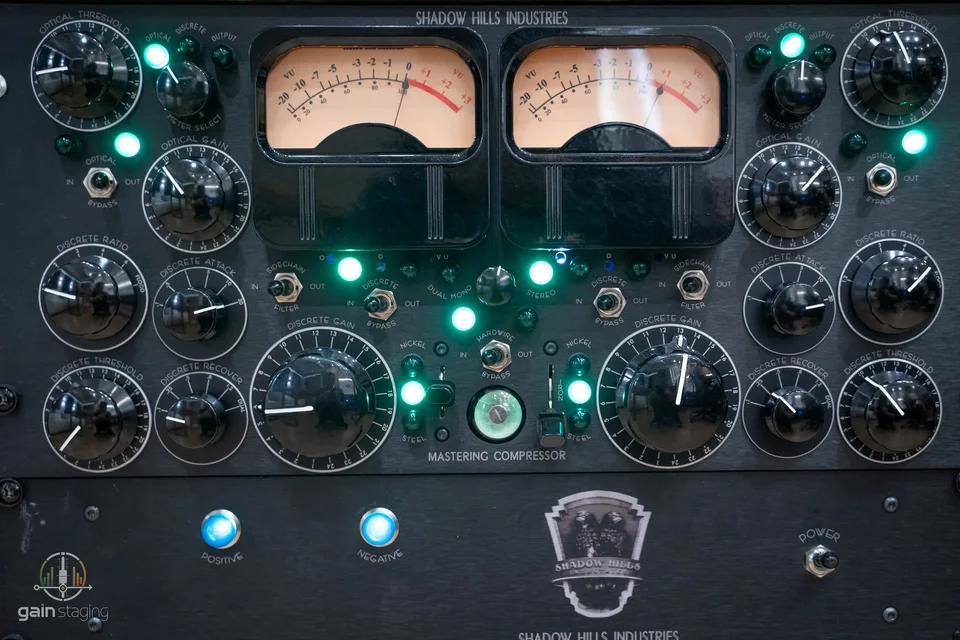
The exterior tells you a fair bit before the lid comes off. The front panel is a thick brushed aluminium plate with large meters, a central green Magic Eye indicator, heavy stepped controls, and a very positive switch action. The large VU meters are not just cosmetic. On a mastering compressor, the meter is part of the operator's control loop. If the meter ballistics or gain-reduction calibration drift, the engineer starts making decisions from bad information.
The panel hardware is expensive, but more importantly it is repeatable. The ELMA rotary switches have firm detents and gold-contact construction in the style normally used where recall accuracy matters. That is the correct part category for this type of machine. A compressor like this will often be reset to known positions for mix-bus or mastering work, and a vague potentiometer or loose selector would be the wrong mechanical language.
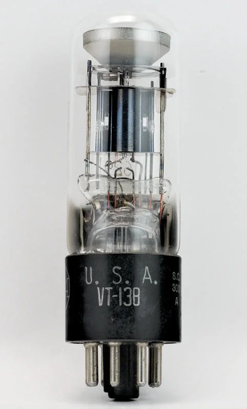
The centre indicator is a VT-138 Magic Eye tube. The VT-138 belongs to the 1629-style electron-ray indicator family, with a 12.6 V heater listed in tube references. It is not a gain device in the audio path. It is a visual indicator, and a very deliberate one: it gives the compressor a second analogue metering language alongside the VU meters. From a maintenance point of view, I treat it like any other display device: heater supply, socket condition, phosphor brightness, and the drive circuit are the things to check when it becomes dim or uneven.
The top-panel hex screws are proud of the chassis rather than countersunk. That is not an audio issue, but it is a real bench issue. Raised screws can mark another unit when equipment is stacked during service or transport. The chassis itself feels robust; the screw detail simply shows that not every mechanical choice is about rack cosmetics.
Internal layout
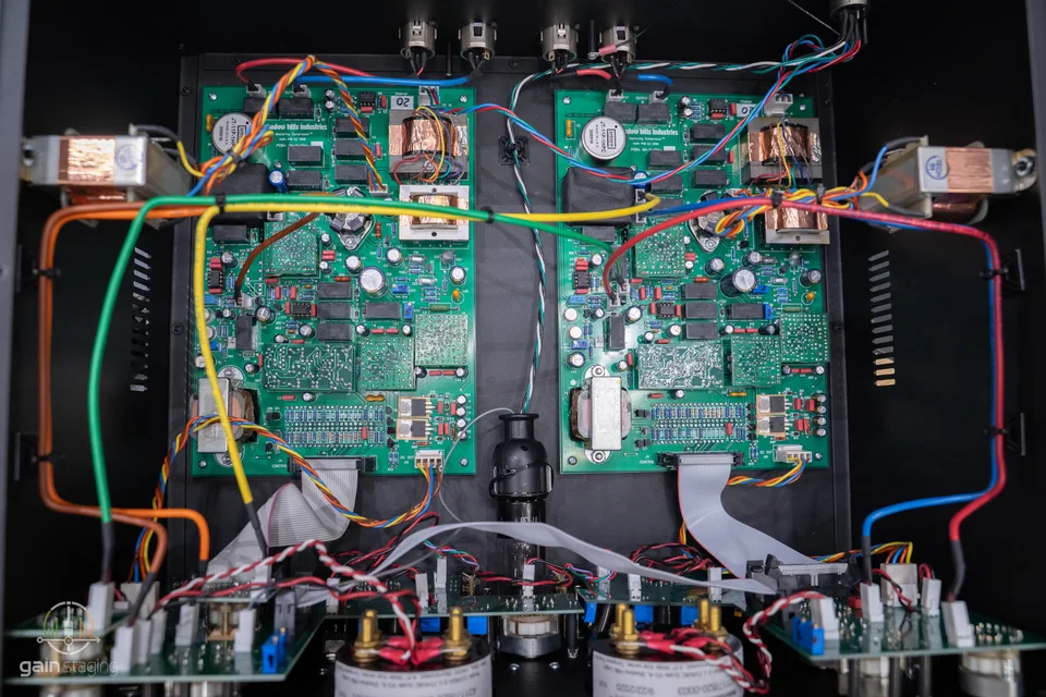
With the lid removed, the machine is easier to read. The external supply keeps the mains transformer and most of the heat away from the audio chassis. Inside the main unit, the dominant objects are the two channel boards, the transformer group, the plug-in amplifier modules, the optical assembly, the discrete VCA module, and the front-panel control board.
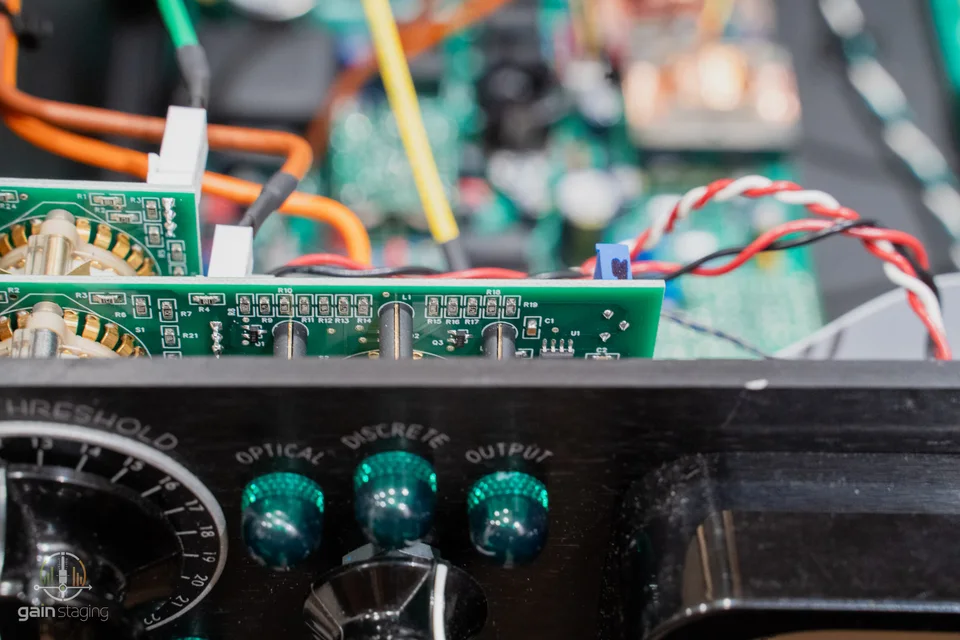
The main audio boards are through-hole and spaced like something designed to be assembled and serviced by hand. That matters. Through-hole parts are not automatically better for audio, but they are easier to probe, easier to replace cleanly, and more tolerant of repeated service than densely packed SMT analogue boards. The audio boards are not minimalist. They look like a product built around discrete building blocks rather than a modern converter-style PCB where most of the work disappears into a few IC packages.
The wiring has the slightly busy look of a transformer-heavy analogue unit. I do not judge that by whether it looks symmetrical in a photograph. I look for strain relief, connector access, separation between low-level signal wiring and power/control wiring, and whether a board can be lifted without desoldering half the machine. On that basis, the unit is serviceable, though not the kind of device I would want to strip casually without photographs and connector notes.
Input transformer and first gain stage
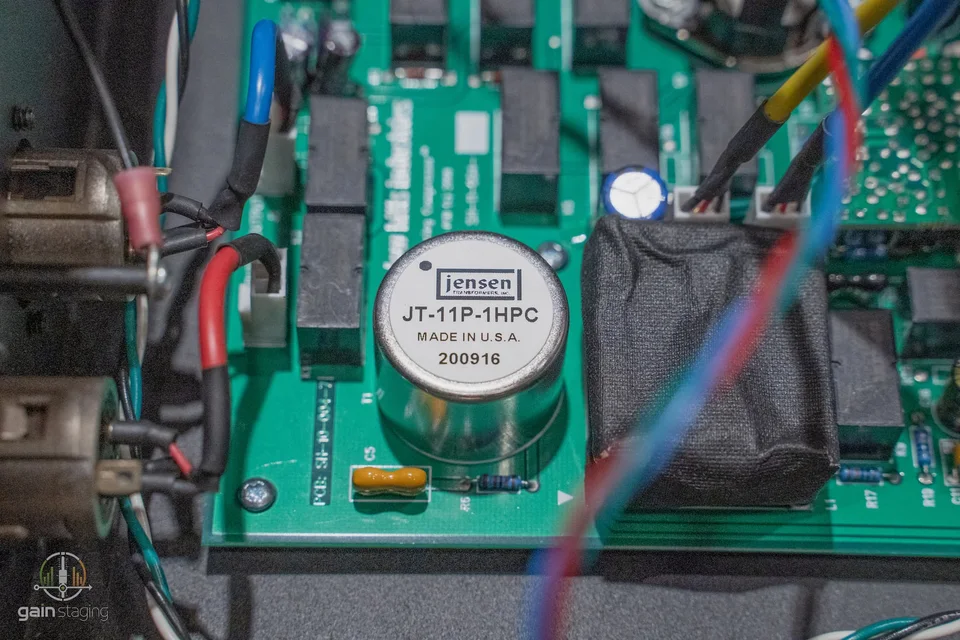
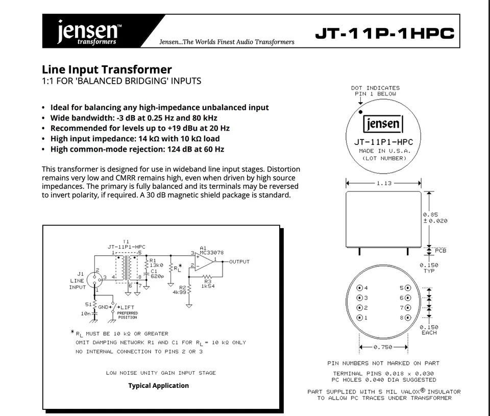
The input transformer in this unit is a Jensen JT-11. Jensen's JT-11P-1 documentation describes a 1:1 line-input transformer intended for balanced bridging inputs. In plain bench terms, that means it is not being used to create a large voltage step-up like a microphone input transformer. It is there to receive a professional balanced line signal, provide galvanic and common-mode behaviour, and set the front of the audio path up in a controlled way.
This matters in a mastering compressor because the box may be inserted between converters, patchbays, console inserts, monitor controllers, or other outboard units with different grounding habits. A good input transformer can make a piece of equipment more forgiving in real studio infrastructure. It can also saturate if driven hard at low frequencies, so it is part of the tone and headroom picture even when it is not being advertised as an effect.
After the transformer, the signal enters the active amplifier structure. The unit uses plug-in discrete op-amp modules rather than ordinary monolithic audio op-amps. Each channel board carries three identical modules. The service advantage is obvious: a module can be removed, photographed, compared, and repaired on the bench without immediately disturbing the main board. The disadvantage is equally obvious: these are proprietary assemblies, so a failure is not solved by dropping in a standard DIP IC.
The module we pulled is a small discrete amplifier built from individual transistors. The small-signal positions include PN4250 devices, while the output/driver area uses MJE181/MJE182-family plastic power transistors. PN4250 is a PNP small-signal transistor type; in a discrete op-amp it would normally live around input, current-source, mirror, or low-level gain duties depending on the topology. MJE181/MJE182 devices are more substantial silicon transistors, appropriate for a small output stage that has to drive the following network with real current rather than simply swing voltage into a light IC input.
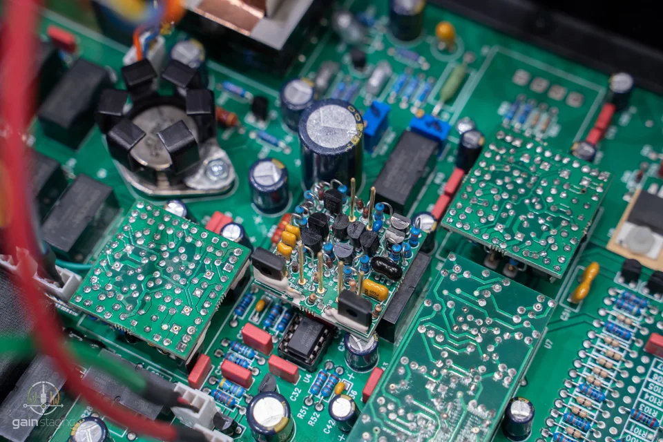
I would not claim a specific 2520, 990, or Neve module copy from a visual inspection. What can be said is more useful: this is a conventional discrete audio-amplifier problem. If it fails, I expect to check transistor junctions, bias conditions, output-stage symmetry, rail current, and whether the module is oscillating under load. It is repairable, but it asks for component-level work rather than board swapping.
Optical gain reduction
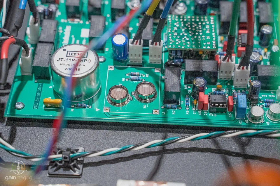
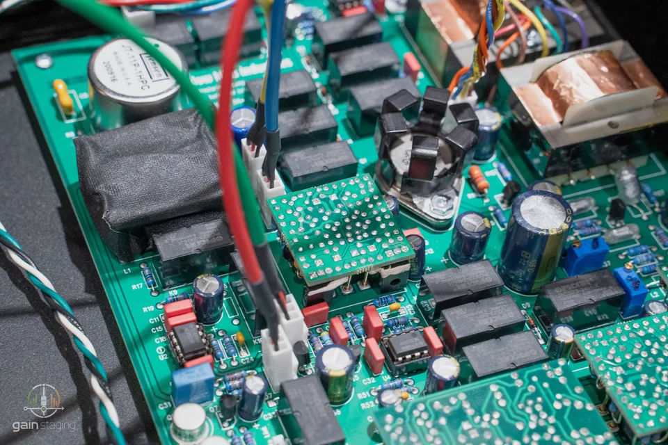
The optical section is the slower gain-control element. The construction is T4B-style in principle, but not a plug-in LA-2A can. Here the opto attenuator is built directly onto the PCB and covered with a black light shield. Under the cover are two light-dependent elements and an electroluminescent panel. That is the important construction detail: the gain-control element is a light source and photoresistive cells, not a VCA chip pretending to be an opto.
An electroluminescent panel does not behave like an LED, and an opto cell does not behave like a precision multiplier. That is why opto compressors have memory. Attack, release, and recovery are partly electrical and partly material behaviour. The cell has history. It remembers illumination in a way a pure electronic gain cell does not.
The two-cell layout is practical. One cell can be used in the audio attenuation path while another can be used for gain-reduction indication or tracking. In a good unit, those two behaviours are calibrated so the meter and the audio attenuation tell the same story. In an old unit, they may not. When servicing this section I would not trust the meter first. I would inject tone, measure actual attenuation, then see whether the VU indication follows it.
Opto assemblies also age in a way that is different from capacitors or switches. The light source can dim, the cells can drift, and the dark resistance/recovery behaviour can change. That is not a design flaw; it is the maintenance profile of an optical compressor.
Discrete VCA section
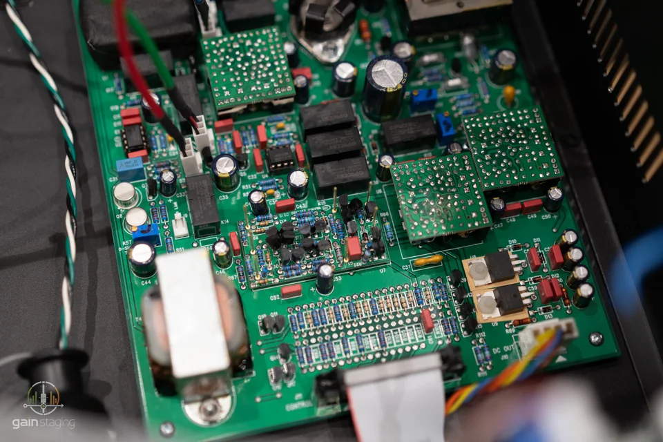
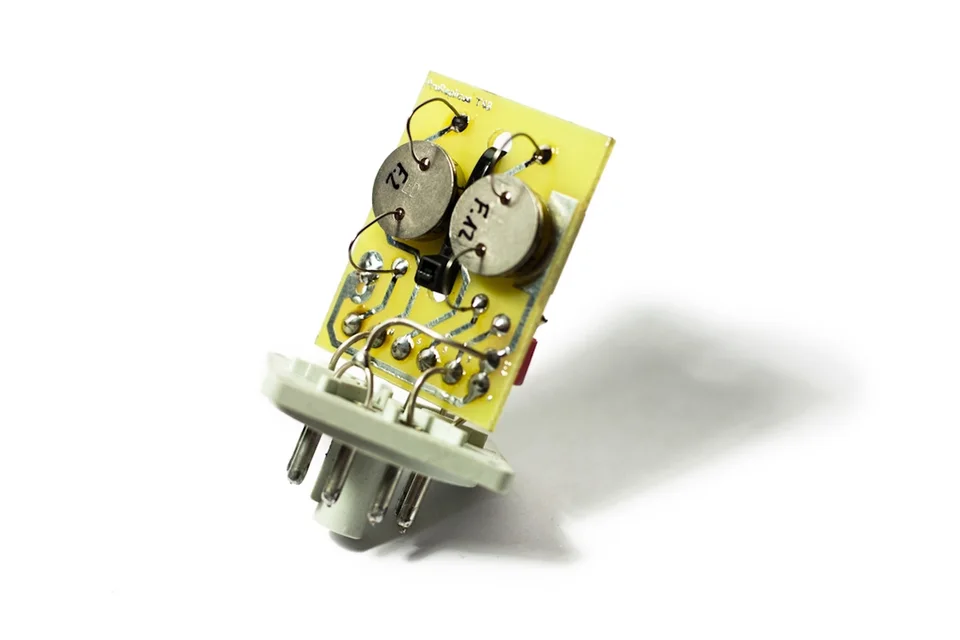
The second gain-control section is the discrete VCA. This is the part I would document most carefully before doing any repair work. It is not a THAT 2181-style modern integrated VCA. It is a discrete gain cell with a physical module format, and its pinout and construction point toward the older dbx VCA tradition.
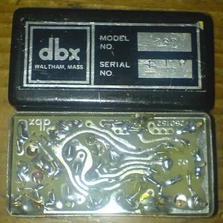
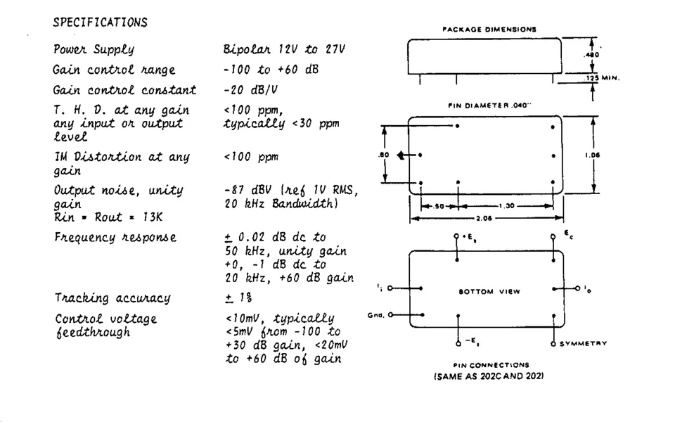
The engineering consequence is large. In an IC VCA, the matching, temperature behaviour, and internal geometry are handled inside the chip. In a discrete VCA, transistor selection, thermal proximity, PCB layout, and calibration all become visible design variables. That is why this kind of module is expensive to build and annoying to repair badly. If one device is replaced with a random transistor from a drawer, the module may pass signal but no longer behave symmetrically under gain reduction.
Sonically, this is also where a lot of the compressor's character can emerge under work. A VCA that is perfectly linear at unity gain can still show its personality when it is being driven, reduced, released, and asked to track left/right in stereo. The proper way to evaluate it is not to stare at the module. It is to measure distortion versus gain reduction, level, frequency, and stereo tracking.
In service, I would check the VCA section with steady tone first, then with stepped gain-reduction amounts. I would look for level offsets, thumps, control-feedthrough, asymmetry between channels, and recovery behaviour that does not match the front-panel setting. A discrete VCA fault can sound like a compressor fault, a control fault, or a power fault, so isolating the module from its control voltage is part of the diagnostic process.
Output transformer and drive stage
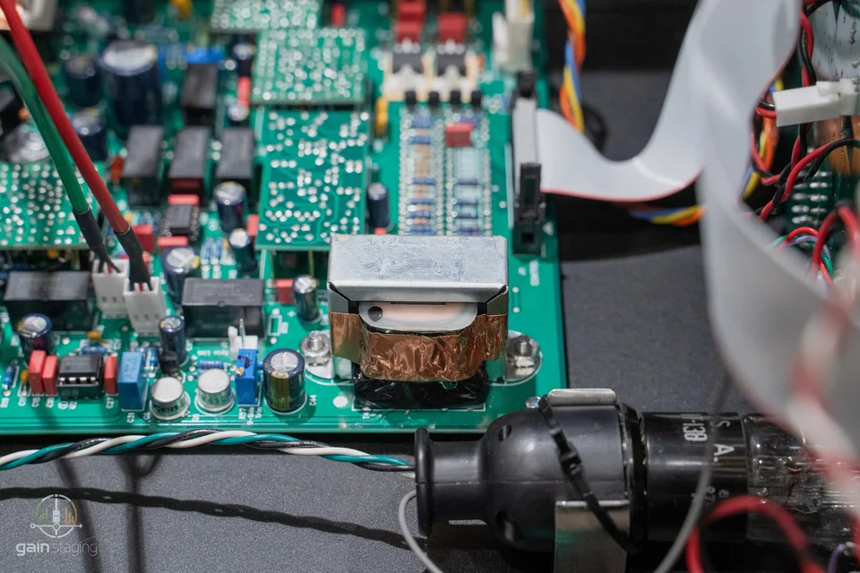
The output side is not a generic electronically balanced output. It is a transformer matrix with three selectable tonal positions: Nickel, Iron, and Steel. We saw several output transformers mounted in the unit, with visibly different construction and core appearance. I would not identify alloy purely by colour, but the design intention is clear enough: the final output stage is meant to offer different magnetic behaviours, not just different labels on the panel.
Transformers do several things at once. They balance the output, provide isolation, define low-frequency headroom, interact with source impedance, and generate their own distortion when pushed. The differences between Nickel, Iron, and Steel are not just frequency-response curves. They involve permeability, saturation behaviour, hysteresis, leakage inductance, and how gracefully the transformer handles low-frequency level. This is why the same compressor setting can feel different when only the output transformer selection changes.

The output area also contains a 2N3055 metal-can transistor. That part immediately suggests the design language of older Class-A transformer-driving stages, especially the Neve BA183 / BA283 family. I would be careful with that comparison: similar parts and architectural ideas do not prove a copied circuit. Looking at the board, though, the 2N3055 does not seem to be the only active device in the output chain. More than one stage appears to build output gain and drive the transformer, so the final level and current delivery are likely shared across several stages. A photo alone cannot establish the full topology, but this is clearly more involved than a simple one-transistor output.

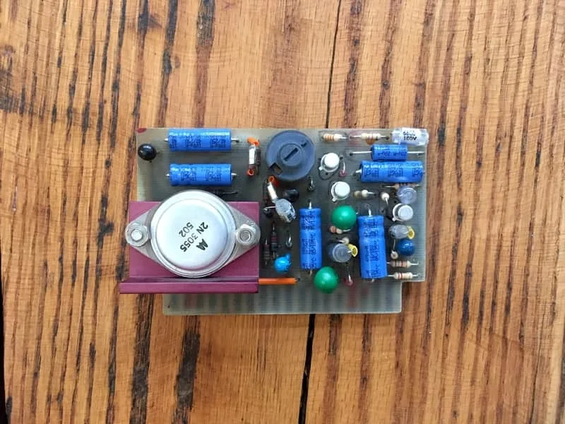
For bench work, this output stage deserves separate measurement. I would look at low-frequency distortion at high level, square-wave behaviour into a normal bridging load, output balance, and whether each transformer position changes level enough to affect recall. If one position sounds dull or asymmetric, the fault may be transformer wiring, switching, drive-stage bias, or a loading issue downstream.
Front-panel control and switching
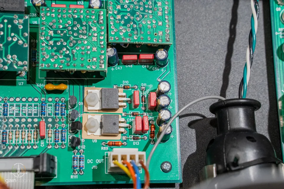
The main audio boards are through-hole and discrete, but the front-panel/control layer is more modern. The panel board uses SMT parts, including DG408 and DG411 analog CMOS switching ICs. These parts are not there to make the audio path digital. They are analogue switches and multiplexers used to route control signals, meter functions, bypass states, and linked behaviour.
This is a sensible way to build a complex analogue compressor. A stereo unit with dual compression sections, meter selection, bypass logic, lamps, and link modes can become a wiring nightmare if every function is carried through long mechanical switch paths. CMOS analogue switching lets the designer keep the user interface repeatable and the wiring shorter.
The service implication is important. If the unit develops a fault where a meter mode is wrong, a bypass state is inconsistent, or the two channels do not link correctly, the problem may not be in the audio path at all. It may be on the control board, in a DG408/DG411 switch, in the logic feeding it, or in the connector between panel and channel boards. That is the sort of fault that wastes time if the technician assumes "analogue compressor" means "all mechanical switching."
Power architecture and grounding
The external power supply is a major part of the design. A linear supply with transformer, rectification, filtering, and regulation keeps mains magnetic fields and much of the heat outside the audio chassis. That is especially welcome in a unit full of transformers and high-gain control circuitry.
The weak point of an external supply is always the interface. The umbilical connector carries the rails and ground relationships that the audio chassis depends on. Poor contact, oxidised pins, insufficient strain relief, or a compromised ground conductor can create faults that appear as hum, intermittent compression behaviour, meter errors, or channel imbalance. On the bench I treat the supply, cable, and chassis as one system.
The power checks I care about are not exotic: rail voltage under load, ripple at the regulator outputs, ground continuity, chassis bonding, and hum components at the audio output. A big analogue compressor can look perfectly healthy inside and still be let down by a tired supply capacitor or a marginal multi-pin connector.
Serviceability
From a repair perspective, the Shadow Hills is not a disposable modern box. The through-hole audio boards, removable op-amp modules, visible transformers, socketed/accessible assemblies, and external PSU all make real bench work possible. That is the good part.
The slow part is calibration and matching. The opto section must be checked for actual attenuation versus meter indication. The discrete VCA must be checked for channel tracking and distortion under gain reduction. The output transformer positions should be measured separately, because a transformer or drive-stage issue can be misread as a compressor issue. The control board must be considered whenever a switching or linking fault appears.
The parts most likely to matter over time are not mysterious: opto cells, the electroluminescent source, electrolytic capacitors in the PSU, mechanical switch contacts, connectors, and any transistor in a heat-stressed drive stage. The machine is built with good parts, but good parts still age.
Measurement context
The June 12 AP captures are useful because they separate several behaviours that are easy to confuse by ear: the three output-transformer positions, the optical section, the discrete VCA section, and both gain-control stages together. The screenshots do not show every test condition, so I would not treat them as a complete specification sheet. They are still enough to show the direction of the machine's behaviour.
Transformer-position frequency response
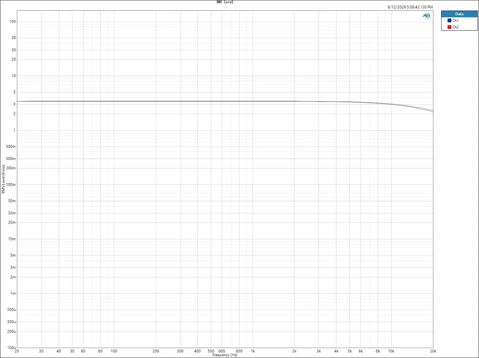
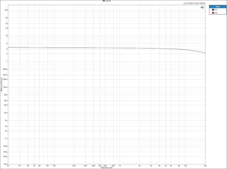
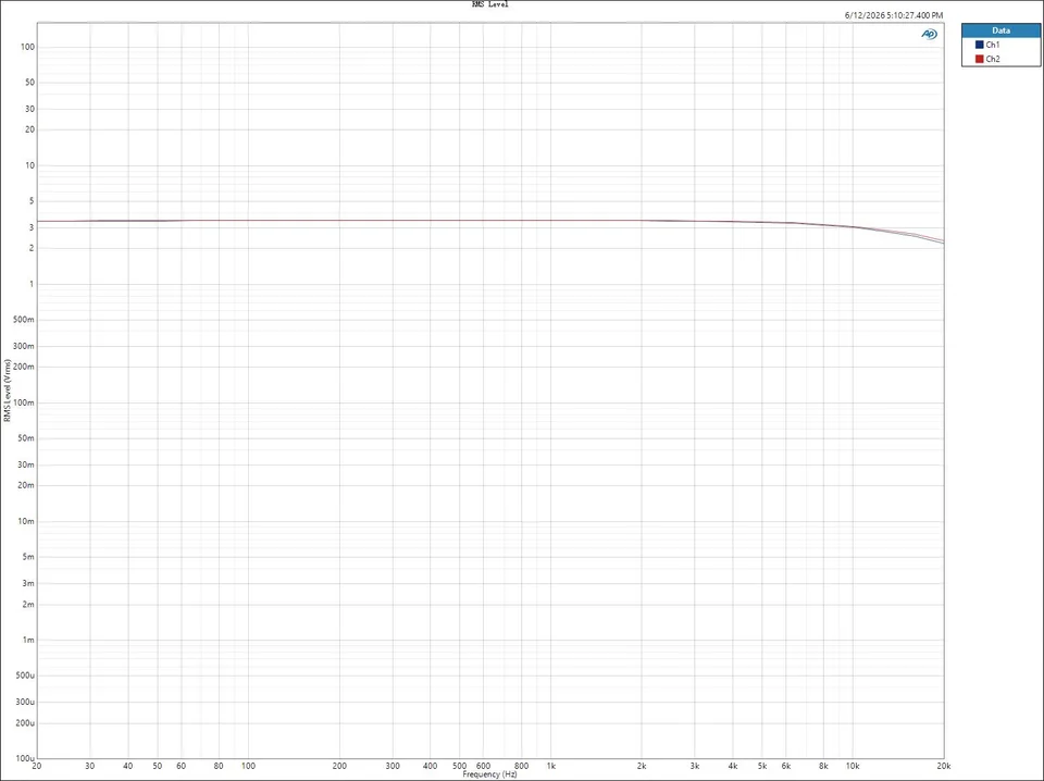
With compression out of the way, Nickel, Iron, and Steel measure much more similarly than the front-panel mythology might suggest. From 20 Hz through the midband the response is essentially flat in all three captures, with the main visible movement happening above roughly 8 kHz. By 20 kHz the traces have gently fallen from the midband level, and the two channels separate slightly at the extreme top end. That supports the practical conclusion: the transformer selector is not a broad EQ switch. Its audible difference is more likely to come from level-dependent distortion, core behaviour, and the way the output stage drives each transformer than from a dramatic static frequency-response curve.
Transformer-position FFT and THD+N
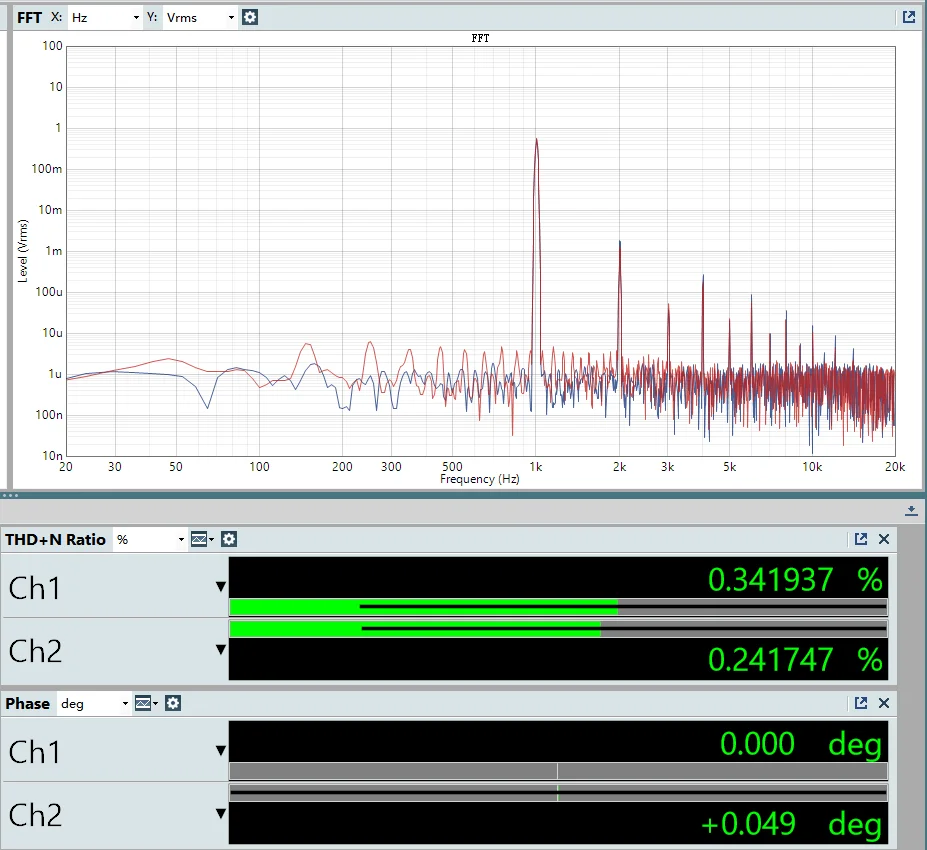
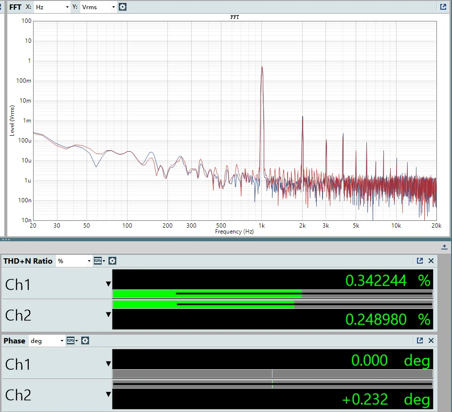
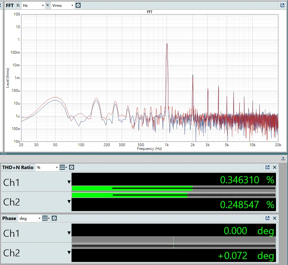
| Transformer | Ch1 THD+N | Ch2 THD+N | Ch2 Phase |
|---|---|---|---|
| Nickel | 0.342% | 0.242% | +0.049 deg |
| Iron | 0.342% | 0.249% | +0.232 deg |
| Steel | 0.346% | 0.249% | +0.072 deg |
The important point is not the third decimal place. The useful observation is that the three positions are close in static THD+N but not identical in spectrum shape. Steel shows a more visible low-frequency residue in this capture, while Iron and Nickel are closer. That fits the construction argument earlier in the article: the transformer matrix should be understood as a magnetic output stage with measurable harmonic behaviour, not simply as three names for the same balanced output.
Optical and VCA gain-control captures
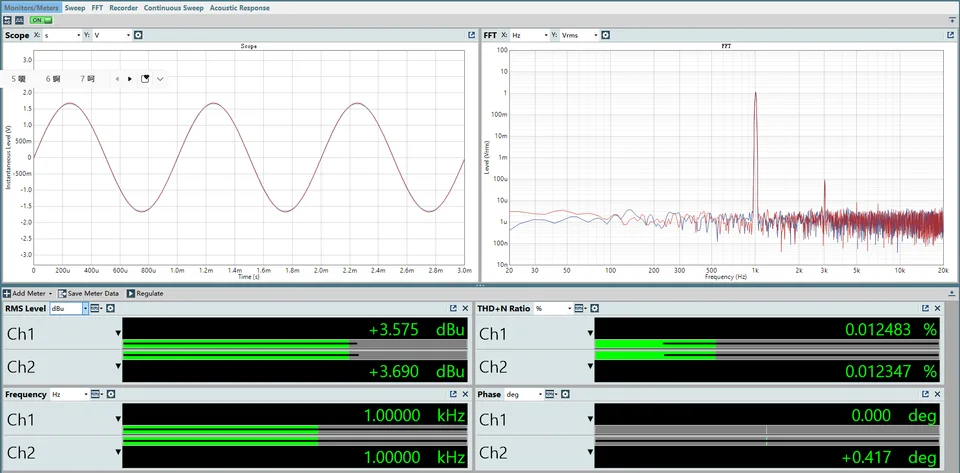
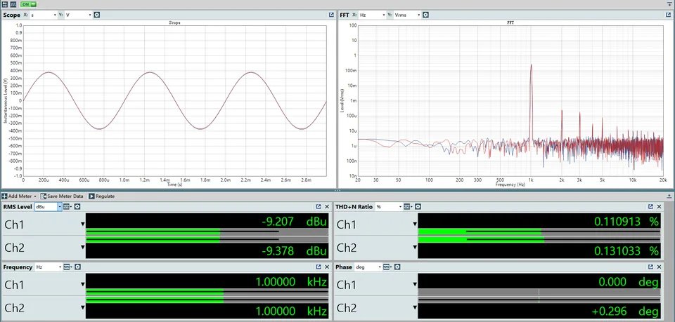
The optical-stage screenshots show the difference between passing signal and actually doing gain reduction. In the no-compression capture, the output meters read about +3.575 dBu on Ch1 and +3.690 dBu on Ch2, with THD+N around 0.0125% and 0.0123%. In the compression capture, the output is down around -9.207 dBu and -9.378 dBu, while THD+N rises to about 0.1109% and 0.1310%. The FFT also shows stronger harmonic structure. That is exactly why the optical section cannot be judged only from bypass or unity-gain measurements: the sonic contribution appears when the light source and cells are actually moving gain.
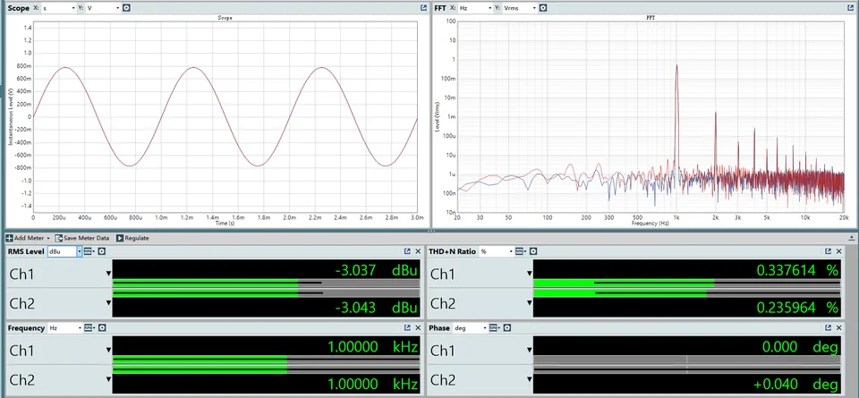
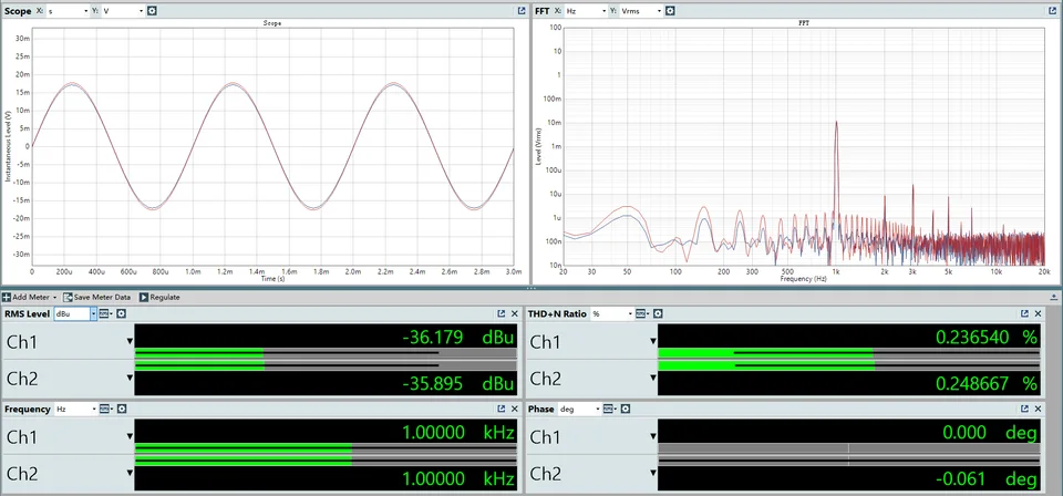
The VCA captures need a more careful reading. With VCA gain at 16 and no compression, the output reads about -3.037 dBu and -3.043 dBu, with THD+N around 0.3376% and 0.2360%. In the full-compression capture, the output has fallen to about -36 dBu, so the THD+N percentage is being heavily influenced by the much lower signal level and the measurement noise floor. I would not use that screenshot alone to rank "better" or "worse" distortion. What it does show is that the VCA's working state changes the harmonic and noise-floor picture dramatically, which is the behaviour that matters in real compression.
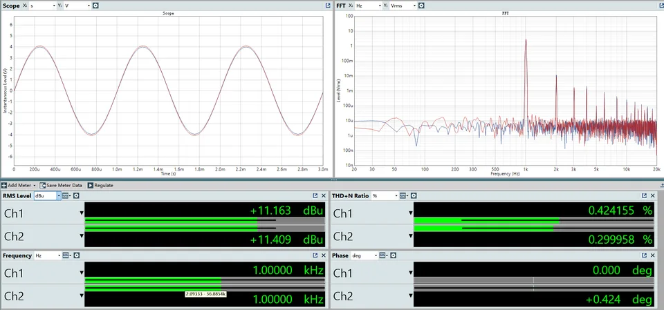
With both VCA and optical sections passing signal but not compressing, the output is much higher in this capture, around +11.163 dBu and +11.409 dBu, with THD+N around 0.424% and 0.300%. This is a reminder that gain staging inside this machine is not a neutral administrative detail. The level through the two gain-control blocks and output stage changes the distortion picture, so recall should include both compression controls and makeup/output gain positions.
| Test condition | Ch1 output | Ch2 output | Ch1 THD+N | Ch2 THD+N | Bench reading |
|---|---|---|---|---|---|
| Optical, Gain 10, no compression | +3.575 dBu | +3.690 dBu | 0.0125% | 0.0123% | Optical path baseline. |
| Optical, full compression | -9.207 dBu | -9.378 dBu | 0.1109% | 0.1310% | About 13 dB lower output; stronger harmonic structure. |
| VCA, Gain 16, no compression | -3.037 dBu | -3.043 dBu | 0.3376% | 0.2360% | VCA baseline in this gain setting. |
| VCA, full compression | approximately -36 dBu | not reported; low signal level affects the reading | Read the spectrum and output level alongside THD+N. | ||
| Optical + VCA, no compression | +11.163 dBu | +11.409 dBu | 0.424% | 0.300% | High internal level changes the distortion picture. |
Channel match and high-frequency zoom
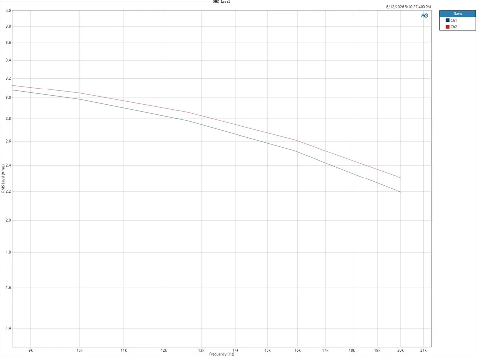

The zoomed plots are useful for channel-matching judgment. Around the 1.23-1.27 kHz window, both channels are nearly ruler-flat and separated by only a small fixed level offset. In the high-frequency zoom, both channels tilt downward toward 20 kHz, with Ch2 staying slightly higher than Ch1. That is not alarming by itself, but it is exactly the kind of small left/right difference that should be documented on a mastering compressor, because it affects repeatability more than a single wideband "sounds fine" check.
Practical studio judgment
On bus duty, the Shadow Hills Mastering Compressor does more than tame dynamics. Its two gain-reduction paths and transformer selection reshape how the signal holds together: Optical rounds out the envelope with a slower pull, while the Discrete VCA keeps transients tight and defined. The Nickel/Iron/Steel setting then adds weight and color on top.
For this test Nickel selected, Optical and VCA both engaged, gain reduction held around 2–3 dB.
The drum bus showed the clearest change: more low-end body and density, with the kick feeling firmer and better placed. A/B'ing bypass against processed, the added low-end texture is obvious, but the transients never collapse.
On the mix bus the effect is subtler. Vocals and instruments separate more clearly without the mix falling apart — everything stays inside the same frame. The low end gains depth and stability rather than just more bass; it feels more organized. That's the real strength here: even at just 2–3 dB of reduction, it's already reshaping the weight, distance, and texture of the whole bus.
Specifications
| Product type | Stereo mastering compressor |
|---|---|
| Primary role | Mix-bus and mastering dynamics processing, gain staging, transformer colour, stereo level control |
| Format | Rackmount analogue dynamics processor with external power supply |
Reader comments
Discussion