 studio electronics, teardown notes, signal path analysis
Compressor
AudioScape MK-609: bench notes and listening notes
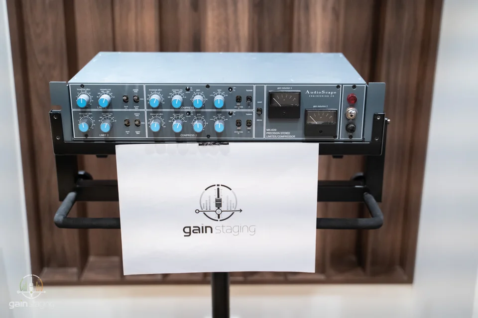
The MK-609 is AudioScape's version of the Neve 33609 diode-bridge compressor. I wanted to see how it was put together and hear how it handled the sort of material that usually works well through a 33609. The teardown, AP measurements and listening notes follow below.
AudioScape has kept the metal knobs and the old-style power switch and indicator lamp. The compressor and limiter have separate controls. There are extra attack settings, plus a side-chain high-pass filter with 50 Hz, 100 Hz and off positions. Those additions remind me of the IJ 609 discussed on DIY forums. The filter is useful on a drum or mix bus when the low end is making the whole signal pump.
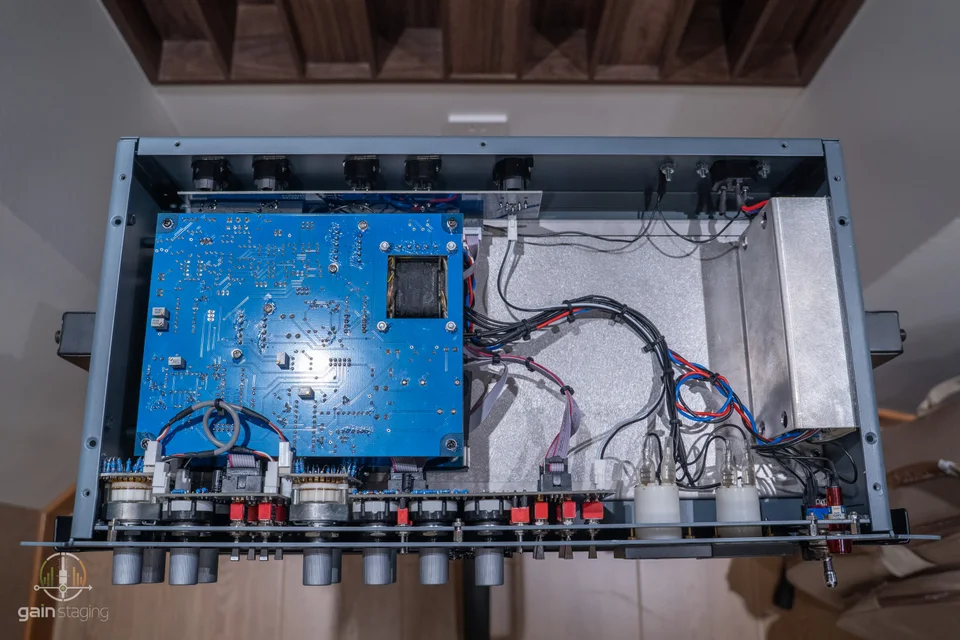
The layout is straightforward. Two audio boards are stacked on the left, with the power supply at the far right, away from the audio circuitry. The ribbon cables are grouped together. There is extensive through-hole construction, and the soldering shows how much of the assembly is done by hand.
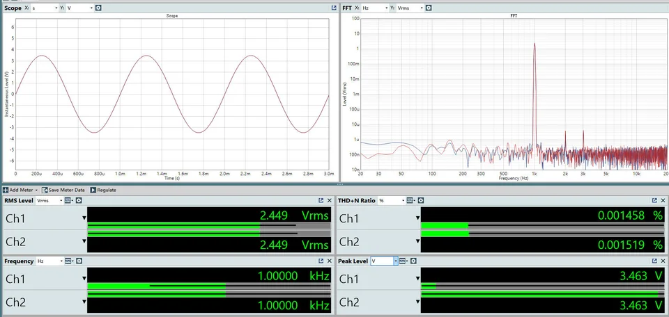
The supply is a switch-mode unit. In use, it is very clean, with no audible power-supply noise. In all bypass, the AP reads about 2.449 Vrms at 1 kHz, with THD+N close to 0.0015% on both channels.
Inside
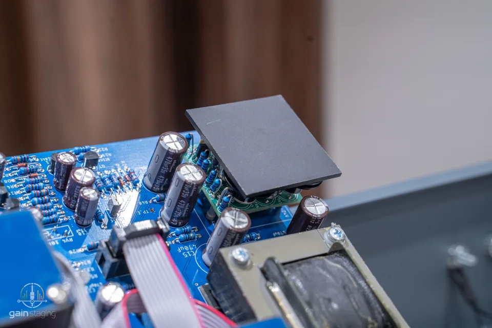
On the main board there are two blue-cased transformers, an output transformer, diode-bridge circuitry and a discrete output amplifier. AudioScape identifies the amplifier cards as BA440C reproductions. The layout is fairly conventional, with the sections easy to pick out and the wiring kept together.
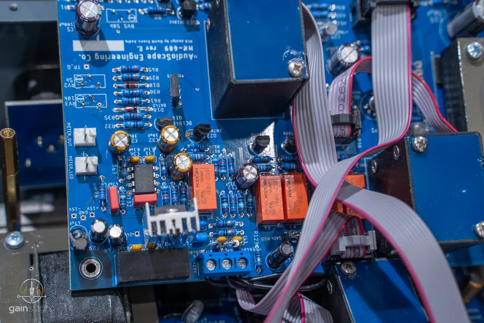
The blue transformer cases have the familiar Carnhill look. Their finish also reminds me of transformers from Poland's IGS and China's DS. AudioScape describes its transformers as custom-wound to the original Marinair / St Ives specification. The output transformer looks hand-wound.
I've used IGS and DS transformers myself. The ones I measured had the required turns ratios and worked in the circuit, but their inductance and DC resistance differed from the old Marinair parts. Carnhill replacements have differences too. Core material and winding methods affect those figures, and the circuit sometimes needs a small change to its impedance matching to suit the transformer. I've seen the same issue with 1073 recreations: the parts list can look right while the sound is still some way off.
In a 33609-style circuit, the audio is reduced to a low level before passing through the bridge, then amplified again afterwards. The side-chain changes the diodes' bias and effective resistance to control the attenuation. That puts considerable demands on the input and output stages. Transformer loading, bridge balance and the gain-recovery stage all affect the result.
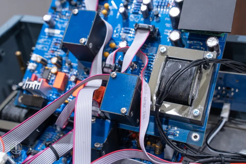
The gain controls on this sample use Swiss Elma rotary switches with gold-plated contacts. They are expensive parts to find in a unit at this price. We saw Elma switches in the Shadow Hills mastering compressor as well. The resistors behind the controls are individually soldered through-hole parts, so there is a substantial amount of hand work here. The Japanese capacitors, relays and OPA2134 op amps are also good component choices.
The heart of this compressor, the diode bridge, appears to use BAT42 diodes, the same type used in the original circuit. This balanced attenuator relies on closely matched diodes. Poor matching can introduce substantial distortion and make the sound unpleasant.
I've run into this when servicing old Neve equipment. New diodes carrying the same part number behaved differently from the old ones, and some inexpensive stock I bought from Chinese websites varied quite a bit. I eventually bought parts from Mouser and selected a matched set, which gave a better result. Diodes cost very little, but sorting them takes time.
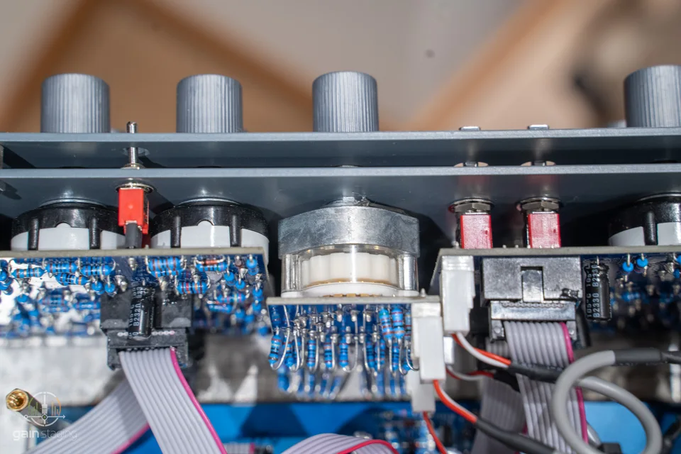
AudioScape uses a similar heatsink arrangement to the classic version, with the two gold-coloured metal-can output transistors fixed to a shared metal plate. The plate carries heat away and keeps the devices in a similar thermal environment. They have retained these expensive parts, which play an important role in shaping the sound. We can't expect modern transistors to behave exactly like their vintage counterparts, but I appreciate the decision to keep this type of device in the build.
When I get the chance, I'd like to compare a range of modern transistors with vintage examples in this stage, looking at both sound and measured performance. A newer version of the same transistor model isn't necessarily the best-sounding choice, because we are easily misled by the identical part number into believing that the same model will produce the same sound.
The original version of 33609 does not include op-amps. The OPA2134 is a modern integrated op-amp, alongside the discrete amplification associated with this design. It may be there for the added side-chain filtering. That would fit with the extra controls; changes in the side-chain can affect how the compressor responds.
Measurements
The 1 kHz capture labelled 0 dBu, gain 5, limiter off and compressor in shows about 0.365% and 0.349% THD+N. In the +20 dBu capture with the same control labels, those readings rise to about 1.71% and 1.87%. Distortion rises sharply with level, and the channels differ. We can certainly expect an increase in distortion under compression in a diode-bridge compressor.


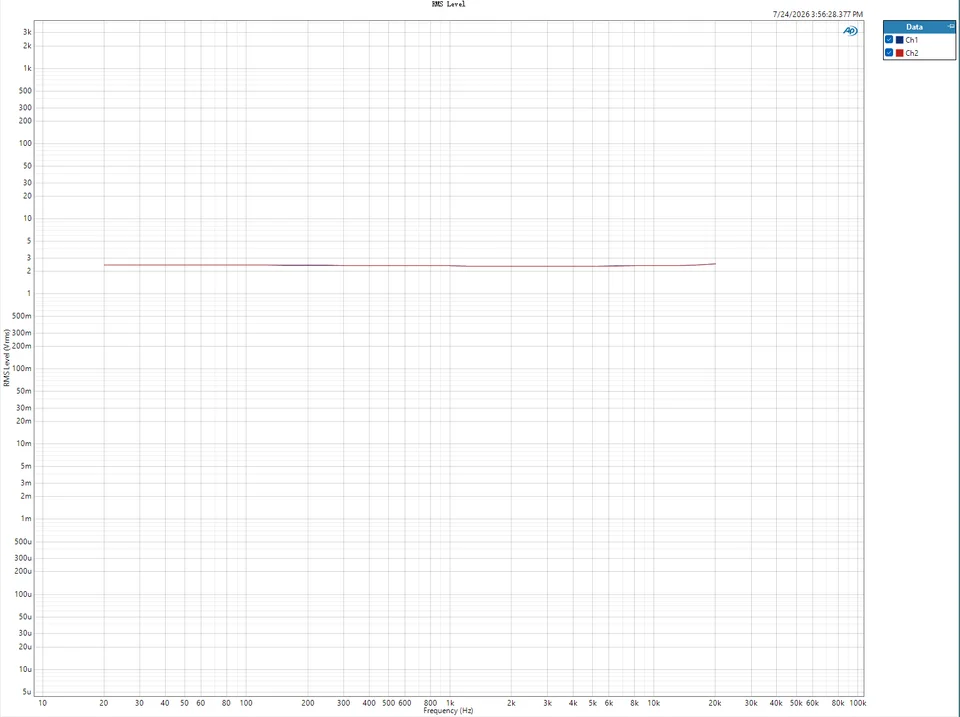
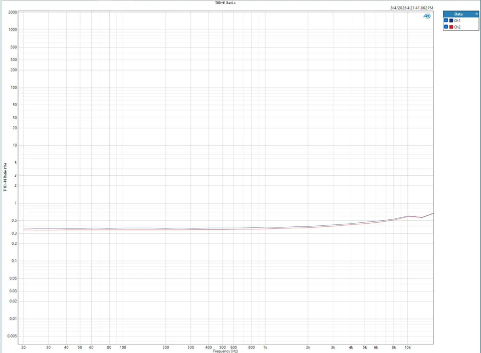
In the 0 dBu frequency sweep, the channels sit close together over 20 Hz to 20 kHz. The broad vertical scale makes small response changes hard to see.
Listening
For listening, I chose material that usually works well through an original 33609. I made several passes on drums and the stereo bus, keeping gain reduction around 2-3 dB.
The overall sound didn't stand out for me. Colour is fairly restrained, although the upper mids pick up a slight character once the input reaches a certain level. What I kept hearing was a loss of depth below roughly 200 Hz when compression was engaged. It happened at different input levels. The low end became lighter and had less weight underneath the rest of the material.
The kick and snare made that easier to hear. Both lost some body and force. The snare in particular sounded thinner and looser, when I had hoped compression would make it firmer. The MK-609 catches the leading edge and rounds the transient, but the shape of the sound afterwards felt off to me. The movement was less natural than in the uncompressed signal.
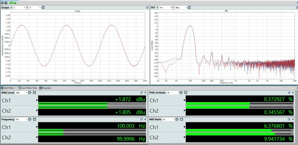
At 100 Hz, the AP capture shows approximately 0.37% and 0.35% THD+N. The second plot below shows THD+N against frequency.
I got on much better with the limiter. On the mix bus it becomes aggressive quickly and can leave the music over-controlled, so I wouldn't use it there as a matter of course. On individual drum tracks, especially kick, it was more useful. The kick tightened up and gained body and weight. That was a sound I could work with.
AudioScape has put money and effort into the build. The sound left me less impressed; I didn't hear a clear step up from products such as Heritage. A circuit like this needs careful component selection and matching, with adjustments to suit the actual parts fitted and put more attention on the transformers and the diode bridge.
The thinner sound and lack of punch could come from low-frequency nonlinearity in the transformers, limited amplifier headroom or a bias issue, or an imbalance or unsuitable operating point in the diode bridge. I'll start by trying a carefully matched set of bridge diodes, then repeat the measurements and listening tests.
Reader comments
Discussion